Linear Condition Properties
Linear conditions describe objects such as walls, foundations, curbs, piping, wiring, etc. - anything that requires is measured by linear foot, inches, meters.
Linear condition - General Tab

|
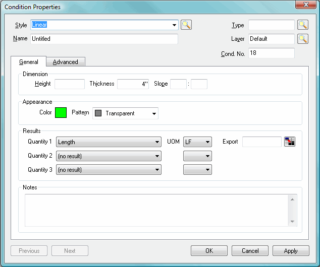
Linear Condition Properties, General Tab | |
|
Style |
Select a Style for the Condition. Type the first few letters of a Style Name to have On-Screen Takeoff fill in the field automatically. Click the arrow, to see a list of all the Condition Styles already saved in this database, then, click on a Condition to select it. Edit the name if necessary, this only changes the name within THIS bid. To view the Style Library, click the Lookup icon |
|
Name |
Name the Condition. It is always possible to go back to the Conditions Properties dialog to change the Name of a Condition if needed. If the condition was created by using a Style, it is OK to change the Name of the Condition, this does not affect the saved Style. |
|
Type |
Condition Types are names given to sets of similar Conditions. They help organize Conditions in a logical manner. Use the preset Types already in the program or create new Condition Types. To create a new Condition Type, click on the Lookup icon, |
|
Layer |
Accept the default Layer or select a Layer from the list. See Layers for detailed information about using and creating layers. |
|
Cond. No. |
Generates automatically, but may be changed to any unique number. |
|
Dimension |
When entering Imperial Dimensions, the last 2 numbers are always considered inches. Metric dimensions are entered in millimeters. For example, an entry of 805 will appear as 8’5”. Enter a Height, Thickness, and a Slope measurement (rise over run) if applicable. |
|
Appearance |
Setting Appearance helps distinguish different takeoff on the Image tab. A Condition's preferences are used to determine how the condition will display on the Image tab, in the Conditions list as well as on the Image Legend, Takeoff and Worksheet tabs. Select a Color and a Pattern. |
|
Results |
There are three quantity areas available. See the chart in Section 7 - Databases for more information on measurements.
|
|
Notes |
This field is for whatever notes to include such as how this condition would be build or any other information that helps identify this condition. |
Linear condition Results
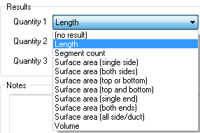
Results are the totals for all the measurements taken for a particular condition. Results shown in the Condition window are for the current page only. To see the total for all pages, review the Takeoff or Worksheet tabs. There are several Linear Results options available:

|
Linear Quantities |
Definition |
|
Length |
The total length of takeoff from one point to another expressed in linear feet, inches or yards. |
|
Segment Count |
The number of linear segments. |
|
Surface Area (Single Side) |
The left or right side of a linear condition.
|
|
Surface Area (Both Sides)
|
The left or right side of a linear condition.
|
|
Surface Area (Top OR Bottom) |
The track or plate surface area of the linear condition.
|
|
Surface Area (Top AND Bottom) |
The track or plate surface area of a top and bottom of the linear condition.
|
|
Surface Area (Single End) |
The end cap of the linear condition.
|
|
Surface Area (Both Ends) |
Both end caps of the linear condition.
|
|
Surface Area (All Side/Duct) |
The top, bottom and two side without the end caps.
|
|
Volume |
The amount of mass of a linear object with thickness and height.
|
Linear condition Properties - Advanced Tab
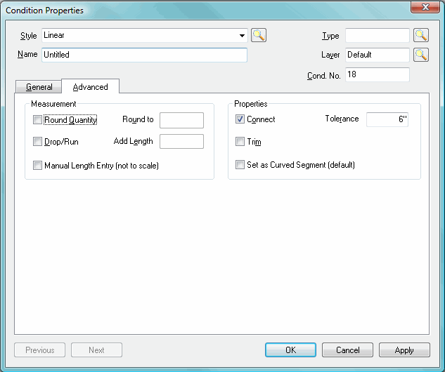
The Advanced tab provides additional settings that can be applied to linear takeoff objects. Measurement provides options for how takeoff is quantified. Options to round measurements to the nearest whole number increment, set additional drop/run lengths for wire or pipe, and manually enter takeoff lengths are available.
Properties provides for additional settings for connecting the corners of two takeoff segments, having a takeoff segment connect to a crossing segment, and setting all segments to give you the ability to curve them as needed.

|
Linear Condition Properties, Advanced Tab | |
|
Round Quantity and |
Indicates the increment to round to. Each segment drawn is rounded up to the nearest increment specified. For example, if this is set to 12", all segments are automatically rounded to the nearest foot.
Example: You have a wall that is 10.08' (or 10' 1", which is 121"). If you round to the nearest 2", your output will be 10.17 LF (showing two decimal places)
How did we get this number?
You have 121 inches, divided by 2 = 60.5 - rounded you have 61 Now take 61 multiplied by 2 = 122 122 divided by 12 = 10.17 LF |
|
Drop/Run and |
Adds additional length (primarily used for electrical and plumbing). If checked and left blank, the drop/run amount is manually entered for each drawn segment. If an entry exists in this field, all segments will automatically have this value added on. |
|
Manual Length Entry (not to scale) |
When checked, the length will need to be manually entered after takeoff segment is drawn - the program is not automatically calculating quantities for drawn segments. Keep in mind, these segments are not to scale. |
|
Connect and Tolerance |
When checked, the program will connect takeoffs if a linear takeoff is drawn near a takeoff object that is perpendicular to it, if the two objects are with the Tolerance setting. |
|
Trim |
When checked, the program will stop a linear takeoff intersecting a takeoff object that is perpendicular to it, On-Screen Takeoff will not draw the 2nd line beyond the first. |
|
Set as Curved Segment |
When checked, all segments drawn with this condition will automatically be set as Curved Segments. See Drawing Linear Takeoff (Curved Lines) for information on using/drawing Curved segments. |


