![]()
12.09.00 using annotation
![]()
Annotations are graphical markups drawn on plans such as: Dimension Lines, Text, Highlight, Hot Links, and Named Views.
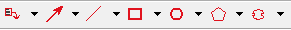
Access the Annotation Tools via the Annotation toolbar.

Dimension lines are simply reference lines drawn on a page to indicate distances between objects and to verify the scale on a page.
Click on the Dimension Line tool ![]() then, simply draw the line in the Image Window.
then, simply draw the line in the Image Window.
To change the formatting of a Dimension line,
Text annotation creates a note on the Image that can call out specific information or alert field staff to special requirements.

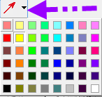
The Highlighter calls special attention to a section of the Image just like using a Highlighter pen. There are 48 colors you can choose for the Highlighter accessible by clicking the drop down arrow.
Click on the Highlighter tool  ,
then click on the plan and drag diagonally away from the starting point
to draw a rectangle - release to finish.
,
then click on the plan and drag diagonally away from the starting point
to draw a rectangle - release to finish.
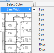
There are seven Shapes available for drawing Annotation, click the small downward facing arrow next to the button to select the color and line width for the shape. Defaults may be set under Tools > Options > Fonts & Colors.
Once a Shape is drawn on the plan, you can adjusts its size and position
by using the Selection Tool ![]() and then adjusting the annotation as needed.
and then adjusting the annotation as needed.
Shape Annotations remember their last setting. For example, if you change the color and line width in Bid "A", then open Bid "B", when you select the same Annotation Shape, it is automatically set to the last color/line width you selected.

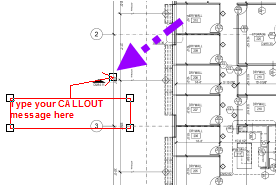
Click the Callout button, then click on the plan to set the starting point (where the arrow will point) and drag away from this spot to draw the callout box. Then, type in the message and adjust font as needed.
![]()
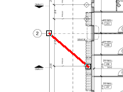
Click the Arrow button, then click on the plan to set the starting point, click again to draw the ending point.
![]()

Click the Line button, then click on the plan to set the starting point, click again to draw the ending point.

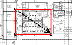
Click the Rectangle button, then click on the plan to set the starting point, hold down the mouse button and drag to the ending point. Release the mouse button to complete the Annotation.

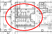
Click the Oval button, then click on the plan to set the starting point, hold down the mouse button and drag to the ending point. Release the mouse button to complete the Annotation.

Click the Freehand (Polygon) button, then click on the plan to set the starting point, click on each corner (vertice) to set additional points and then double-click to complete the Annotation.
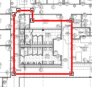
Just like Area takeoff, you cannot draw an 'uncloseable' polygon or cross lines. If On-Screen Takeoff generates a 'thunk' sound, that indicates that the segment cannot be drawn or the polygon cannot be closed. Press ESC on your keyboard to back-up to a point where you have not crossed lines or drawn a polygon shape that cannot be 'closed'.

Click the Cloud button then click on the plan to set the starting point, click on each corner (vertice) to set additional points and then double-click to complete the Annotation.
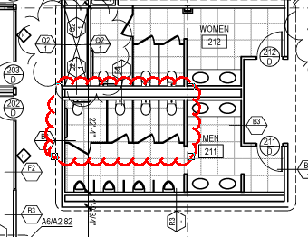
Just like Area takeoff, you cannot draw an 'uncloseable' Cloud or cross lines. If On-Screen Takeoff generates a 'thunk' sound, that indicates that the segment cannot be drawn or the Cloud cannot be closed. Press ESC on your keyboard to back-up to a point where you have not crossed lines or drawn a Cloud shape that cannot be 'closed'.
![]() Hot Links & Named Views video
Hot Links & Named Views video
Hot Links and Named Views work together and provide an easy way to navigate through the project. Hot Links are shortcuts to a Named View. Named Views are defined locations in a project - usually a detail of a drawing referenced on a page being taken off.
A Hot Link provides a way to quickly jump to a Named View from any other page in a Bid.
Hot Links work in the Image Window Window (where takeoff is done) and in the View Window.
To create a Hot Link
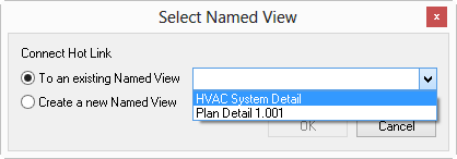
By default, On-Screen Takeoff opens Named Views in a separate View window. To open a Named View in Image Window (where images/takeoff are displayed), click Tools > Options and uncheck the "Open hotlinks in separate View Window" button.
A Named View can be an entire page or any part of a page or for a particular zoom level. A single page can have multiple Named Views created on it. This is especially useful when creating a Named View based on construction schedules or details (for example, for Wall Finish Schedule, Door Schedule, Flooring Schedule, etc).
To create a Named View:
Named Views are accessible in the View Window, see View Window in Program Tabs for information on this feature.
To open a Named View:
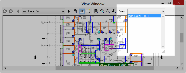
The View window is for reference only. To perform takeoff or to draw any Annotation, return to the Image window.