Linear takeoff is anything measured with a line (even a curved line) with results such as foot, yard, meter. Measurement such as walls, gutters, pipes, and wiring are examples of Linears. Depending on how you setup the Linear Condition, On-Screen Takeoff can calculate linear measurement, of course, but also area (using the Condition's Height) and volume (using the Condition's Height and Thickness). See Related articles for information on setting up Linear Conditions.
Before
drawing any
takeoff, set and verify the scale on every page. See Related Articles for more information.
By default, when you draw linear and area takeoff using a mouse, On-Screen Takeoff 'snaps' the mouse position to 15 degree angles and indicates when you are at 90 degrees to the previously drawn segment. These features makes taking off common corners easier, but you may not want your lines to 'snap' to a particular degree all the time.
- To override "Snap Angle", hold down the <Shift> while drawing your segment. This disables Snap Angle only while <Shift> is pressed.
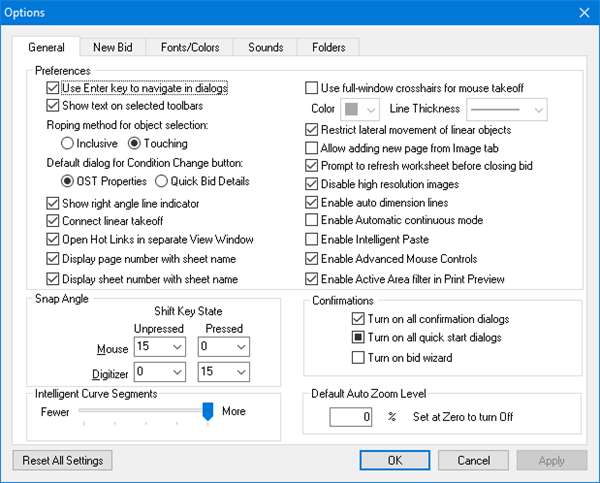
- To disable Snap Angle completely or to disable the Right-angle Indicator, change your settings in Tools > Options. Set the Snap Angle settings to a lower degree and disable the Right Angle Indicator - whichever you choose. See Related Articles for details on setting program and user options.
Linear takeoff is drawn using one of two modes: Normal and Continuous.
Drawing "Normal Mode" Linear Takeoff
Normal Mode is best for individual segments or linear objects such as non contiguous interior walls. To take off a linear object in Normal mode,
- Select a Linear Condition from the Conditions List, the cursor changes to the takeoff mode indicator

- Click the first point for the linear object
- Hold down the left mouse button
- Drag the cursor to the end point of the linear segment (while holding down the left mouse button)
- Release the mouse button to close (complete) the object
Repeat for each segment of linear
takeoff.
This is fine for drawing just a few, disconnected segments, but to takeoff numerous, connected segments, use "Continuous Mode"...
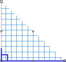
Drawing "Continuous Mode" Linear Takeoff
Continuous Mode is the best way to draw several connected segments, such as all the exterior walls of a building or to follow the contour of a undulating wall (such as an "S" curve). Simply click the start point, then click any point to draw a line between them, continuing on for each segment, then double-click the end point to 'close' or complete the takeoff.
Automatic Continuous Mode
Under Tools > Options there is an option to enable Automatic engagement of Continuous Mode (this setting is uncheck (the feature disabled) by default).
- If this option is enabled, when you are drawing takeoff, when you click and hold your mouse button down, you automatically engage "Continuous Mode". Once the automatic Continuous Mode engages, hit <ESC> to turn 'off' Continues Mode, or double-click to close (complete) the takeoff.
- If you’ve disabled this option, to engage Continuous Mode, you click the "Continuous Mode" button
 on the Takeoff Mode toolbar.
To take off a linear object in Continuous mode,
Single Segment
- Select a Linear Condition from the Conditions List, the cursor changes to the takeoff mode indicator
- Click the first point for the linear object
- Click the end point of the linear segment (do not hold down the left mouse button)
- Double click at the terminating point
Repeat for each segment of linear takeoff.
Straight, connected segments
- Select a Linear Condition from the Condition List
- Click the first point for the takeoff object(s), this anchors the starting point
- Click the end of the first segment (do not hold down the mouse button)
- Click the mouse or stylus, the first segment is drawn
- Click the end of the next segment
- Click the mouse or stylus, the second segment is drawn
- Repeat until all segments are drawn
- Double-click the mouse or stylus to complete (close) the final segment
Contours
To takeoff a linear object freehand in Continuous mode, for example to make a circle or follow a curve,
- Select a Linear condition from the Condition List
- Click at the first point for the takeoff object(s), this anchors the starting point
- Hold down the left mouse button (or keep the stylus pressed onto the screen)
- Draw a line that follows the contour (while holding down the left mouse button)
- Double-click the mouse or stylus to complete the contour line
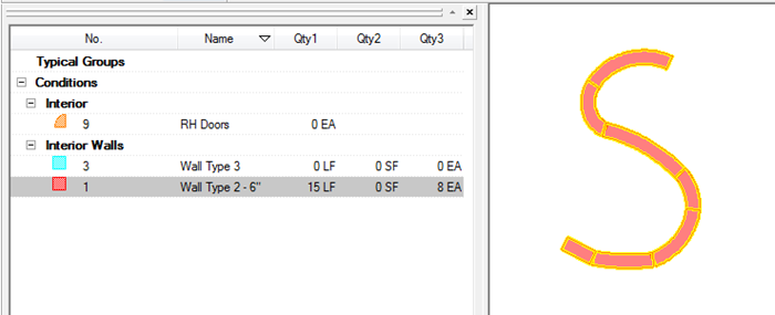
On-Screen Takeoff converts the curved line to straighter, shorter segments based on Intelligent Curve Settings. Each of these segments becomes a separate segment and is reported in the Condition's Quantity Results if "Segment Count" is selected. See below to fine tune the "Intelligent Curve" feature.
This is not the same as curving a linear segment (which remains as a single segment), covered in the next few articles.
Intelligent Curve Settings
The Intelligent Curve setting controls how the program converts curved (continuous mode) linear takeoff to straighter, shorter segments.
Example:
Select a Linear Condition
Click the Continuous Mode button (or, hold down the left mouse button)
Draw some takeoff - in this example, an S shaped object (keep holding down the left mouse button to draw this shape)

Double-click to end this takeoff, On-Screen Takeoff converts this object to several straighter segments
To adjust the number of segments, select Tools > Options > General and then adjust the slider in the Intelligent Curve Segments field. This range determines the number of individual segments to which the linear object is converted.
Under Tools > Options, there are several options that control how you draw linear takeoff. Please see Related Articles for more information on setting your User Preferences and Options.
If you want a curved segment to remain as one object, you draw an Arc...


 Multi-Condition Takeoff