|
|
| |
| |
OST - 05.05 Creating Area Conditions (to measure surface areas such as ceilings, floors, slabs, etc.)
| Views: 3899 Last Updated: 02/29/2024 06:51 am |
100 Rating/ 1 Voters
|

|
| Be sure to rate this article 5 Stars if you find it helpful! |
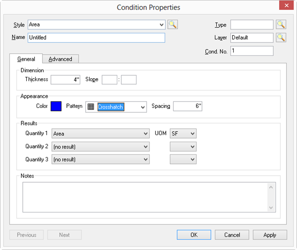
You use Area Conditions to measure objects such as slabs, ceiling tiles, flooring, roofs, and facades that require a measurement for total square footage (or square meters, etc.). An Area Condition can calculate volume for objects such as concrete slabs, poured walls, and landscape fill if you specify a "Thickness" and, of course, you can select "Perimeter" or "Grid Length" as one of your Results to account for framing or rebar. Area Condition - General TabThis is basic information about an Area Condition such as thickness, color/pattern and the Quantity results required. We covered Style, Type, Name, Layer, and Condition Number in Related Articles. - The Dimension section includes settings for Thickness and Slope.
- In the Appearance section, you set the Color and Pattern of the takeoff objects drawn with this Condition. If you select a non-solid/non-transparent Pattern, you are provided with a field to set the spacing of the pattern. Appearance settings determine how objects drawn with the Condition display on the Image Tab, how each Condition looks in the Conditions list, in the Image Legend, and on the Takeoff Tab and Worksheet Tabs.
- Select which Results you want displayed in the Conditions Window.
- Add whatever notes Notes to document additional details about this Condition such as construction information or material notes.
| Field | Description |
|---|
|
| Dimension | - Thickness - Allows On-Screen Takeoff to calculate Volume. Handy for concrete slabs, insulation and bedding.
- Slope - Used primarily for roof takeoffs. On-Screen Takeoff takes into account the Rise:Run or Run:Rise. If performing takeoff on an orthographic project (using a 'birds eye' view) use Rise:Run for slope, if taking off an area using an elevation plan, use Run:Rise for slope. Only area and volume are adjusted for slope. See below for a chart of Area Slope Conversions conversion factors to convert degrees to Rise:Run. We cover slope in detail in Related Articles.
| | Appearance | Appearance settings determine how objects drawn with the Condition display on the Image Tab and how each Condition looks in the Conditions list, in the Image Legend, and on the Takeoff Tab and Worksheet Tabs. Select a Color, Pattern, and Spacing (see next row). | | Spacing | Enter a measurement to set the spacing to be used in non-solid and non-transparent patterns. This only affects how the takeoff is displayed and has no bearing on measurement quantities. | | Results | You can select up to three Results for each Condition. Quantity "1" should be considered required and its default is Area (SF). (For Quantities 2 and 3 to show on the Worksheet Tab, you must select a valid Quantity 1) There are three Area results that are special and depend on the Grid as set on the Advanced tab: - Grid Length (Visible): Calculates the cumulative length of the grid.
- Tile Count (Average): Calculates the number of tiles based on area and tile size. For example, for an area of 800 SF with a tile size of 8 SF (ex. 2 X 4 Acoustical Tile) results in a tile count of 100.
- Tile Count (Visible): Calculates the number of tiles based on grid alignment and orientation rather than on area and tile size. While this adds waste to the takeoff, it can be helpful in more accurately projecting labor and material needed if an architect or owner calls for a specific installation of materials.
| | Notes | This field is for whatever notes to include such as how this condition is built or any other information that helps identify this Condition. |
Area Condition ResultsResults are the totals for all the measurements taken for a particular condition. Results shown in the Condition window are for the current page only. To see the total for all pages, review the Takeoff or Worksheet Tab. There are several Area Results options available: 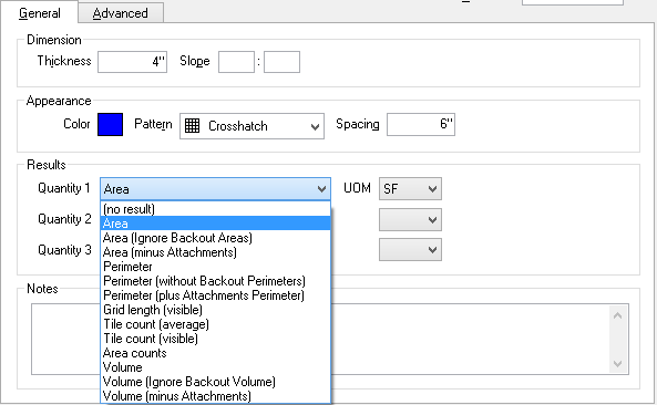
The Result selected determines which Units of Measure are available. | Result | Definition | Calculation |
|---|
| Area | The surface area of an object drawn with this Condition less the surface area of any backouts but ignoring the area subtractions of any attachments | (A)-(BA) | | Area (Ignore Backout Areas) | The surface area of an object drawn with this Condition without subtracting backouts or the area subtractions of any attachments | (A) | | Area (Minus Attachments) | The surface area of an object drawn with this Condition, less the surface area of any attachments and less the surface area of any backouts | (A)-(BA)-(AA) | | Perimeter | The linear measurement around an object drawn with this Condition (for example, trim or molding around flooring or the forms needed to pour concrete) - includes Backout perimeters but does not include the perimeter of any attachments | (L)+(BL)-(AL) | | Perimeter (Without Backout Perimeters) | The linear measurement around an object drawn with this Condition, not including the perimeter of any Backouts | (L)-(BL) | | Perimeter (Plus Attachment Perimeters) | The linear measurement around an object drawn with this Condition including the perimeter of any attachments | (L)+(AL) | | Grid Length (Visible) | The linear measurement of grid lines within an object drawn with this Condition if Grid property selected - does not include any perimeter | (GL) | | Tile Count (Average) | The Calculated average count of tiles within an object drawn with this Condition expressed as an each count | (Square foot of area condition) ÷ (Square foot of tile based on Grid) | | Tile Count (Visible) | The actual count of tiles adjusted for the grid alignment; counts each partial or complete tile as one whole tile; expressed as an each count | Count of visible tiles/partial tiles | | Area Counts | The number of objects drawn with this Condition on the Current page (cumulative total on the Takeoff and Worksheet Tabs) | Count (Area objects) | | Volume | The amount of mass of an object drawn with this Condition less the volume of any backouts but ignoring the volume subtractions of any attachments | (Surface area (sq ft) x Thickness)-(BV) | | Volume (Ignore Backout Volume) | The amount of mass of an object drawn with this Condition ignoring any Backout volumes and ignoring the volume subtractions of any attachments | (V) | | Volume (Minus Attachments) | The amount of mass of an object drawn with this Condition less the volume of any attachments and less the volume of any backouts. | (V)-(AV)-(BV) |
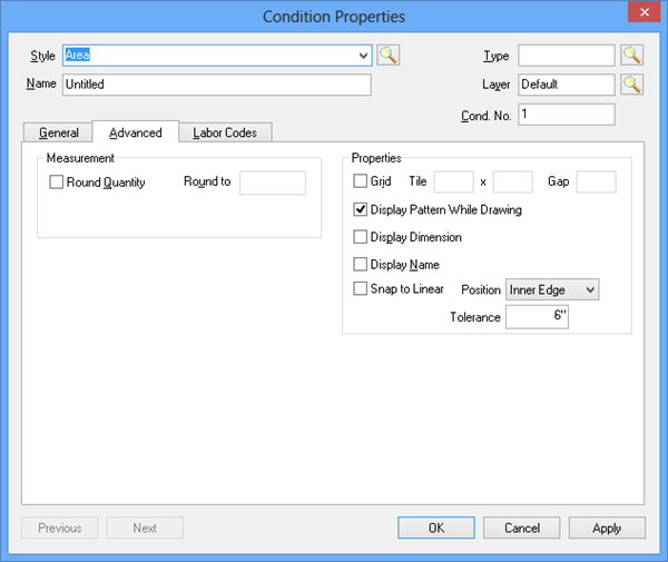
Area Condition Properties - Advanced TabThe Area condition Advanced Tab contains options for rounding, using a Grid, and snapping, as well as display options. The Measurement field provides a setting for rounding each segment of an area takeoff to the nearest whole number increment. "Rounding" an Area Condition/takeoff does not round up overall square footage results for the condition/takeoff object, each Segment is rounded, according to how you setup the Condition. It is very important to understand how Rounding area segments works before using this feature as it can dramatically affect takeoff results. See Related articles for detailed information. See the next article for examples of Rounding settings affect Condition Results. Advanced Properties fields are used to: - Setup a Grid for quantifying a tiled or bricked area expanse
- Display the Condition's Pattern while drawing the takeoff (ON by default, it can be handy to turn this off when taking off a large or complicated area - when "OFF" displays the outline of the area takeoff until the area is 'closed', then the pattern is filled in)
- Display Dimension - when activated, On-Screen Takeoff places a small label in the center of each area taken off with this condition showing the individual takeoff objects Quantity 1 result
- Snap to Linear - automatically connects area takeoff to nearby Linear takeoff based on the Position and Tolerance set.
| Option | What it does/How it is used... |
|---|
|
| Round Quantity and Round to | Select the Round Quantity box to apply this feature and enter a value to which to round each segment taken off using this Condition. We cover rounding in the next article - please do not use it until you understand how it works. | | Grid/Tile/Gap | Check the Grid box then, type in the size of the tiles. Next, enter the gap between each tile. This creates a grid pattern at the specified size for the area takeoff object. The gap setting controls the thickness of the lines for the grid area - just like an acoustical ceiling grid. | | Display Pattern While Drawing | When taking off large or complex areas, it is sometimes easier to suppress the display of the actual pattern while drawing the area. Once the area is 'closed' - it fills in with the appropriate fill pattern as set on the General Tab. (checked by default) | | Display Dimension | With this box checked, the Quantity 1 result appears in the center of each area takeoff object drawn, as in the example below. 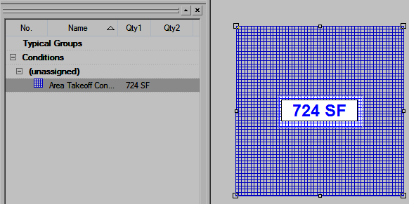
If dimension boxes are too big or too small, adjust the Font Size to reduce the size. See Related articles for information on Adjusting Annotation. | | Display Name | When checked, a label showing the Condition Name is placed next to each takeoff object drawn in the Image window.
To adjust the Font/Color of the label, select an individual piece of takeoff and the Text Format toolbar displays.
Each label is adjusted separately. Each label is limited to 9 characters, if your Condition Name exceeds 9 characters, it is displayed as "Condition...". | | Snap to Linear | Put a check mark in the Snap to Linear box and then choose a position and tolerance for the area takeoff. This feature makes drawing area takeoffs much easier - the area takeoff 'snaps to' nearby linear condition so it does not have to be drawn as precisely. This feature makes it easy to auto-fill rectangular rooms. Once a room is already outlined with linear Condition takeoff, double-clicking within that space auto-fills with the selected area Condition. | | Position | Determines where the perimeter segments of area takeoff locate themselves in relation to the nearest parallel linear object when using "Snap to Linear" - Inner Edge - places the area object’s perimeter on the inner most edge of the closest parallel linear takeoff object.
- Center - places the area object’s perimeter on the center of the closest parallel linear takeoff object.
- Outer Edge - places the object’s perimeter on the outer most edge of the closest parallel linear object.
| | Tolerance | Set for the distance that the snap to linear feature uses to snap the area takeoff to the linear takeoff. For example, if set to 1' 6", then when area takeoff is drawn within 1' 6" of a linear takeoff object, the area would automatically to the linear takeoff. |
|
|
|
|

 Accounting for Slope in a Linear Condition